Monday, 6 July 2015

March 2014

Lots of sundry stuff prior to glassing the cabin and cockpit area.

Window shape and location sorted out and formed (the coated plywood rings are the reinforcing pieces for inside the windows). Deck plate hatches trial fitted. Main hatchway formed. I decided on a hinged hatch top which would open up access to the cabin plus the usual drop in washboards for the vertical parts.  I formed the hatch top with the same camber as the cabin roof , just for looks but the finished result is barely noticeable (see later photos).
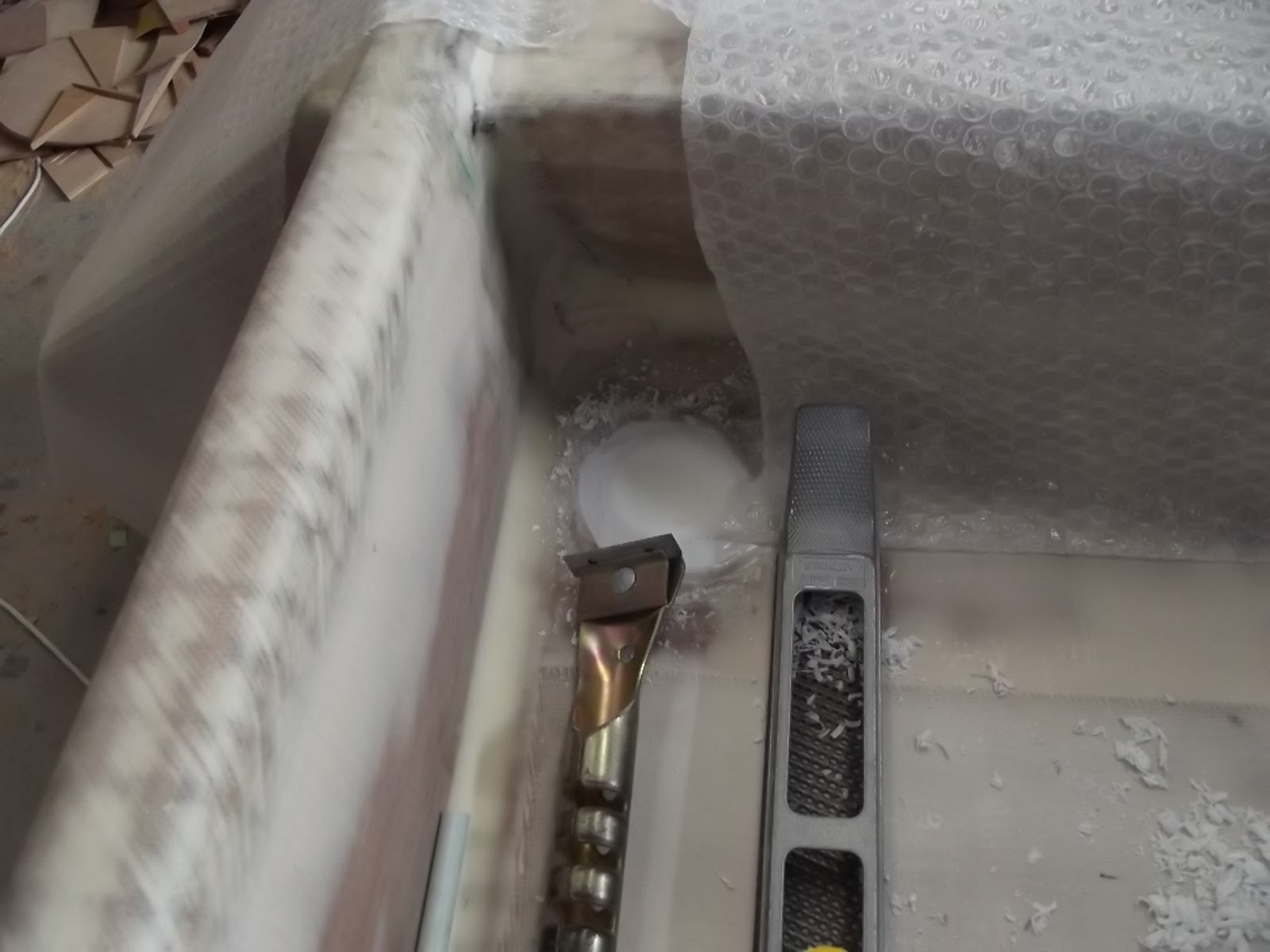
 Cockpit seats closed in. Drain holes in cockpit floor added. One in each corner of the cockpit floor about 100 mm in from corner, to allow working space. My drain holes are 40 mm diameter. First I made an oversize hole with 55 mm hole saw on my drill, filled it with epoxy filler, faired it off , and then re drilled it with the smaller (40 mm) hole saw. This gave a clean epoxy edge , unlikely to get damaged later. Possibly later I may add one way drain plugs, or some sort of deflectors underneath to stop water being forced up.

Photo of the interior: tons of storage


December 2013

Extra reinforcing glass tape at bow area- crossbeam edges, bow net tubes, front curved panel .
Cabin sides  fitted. Cabin roof fitted. Roof is 9 mm ply which is scarf joined in situ at time of fitting. Lots of dry, trial fitting here. At the rear of the cabin sides and roof, where they overhang the rear panel (back wall of cabin) I added a double thickness of plywood to strengthen this area. This was not in the plans but I thought it was good insurance.


November 2013

Front crossbeam and bow net holder permanently mounted and coved. The sloping transom panels fitted finally. The black composite pieces at the rear beam will be the mainsheet attachment point plus providing extra attachment points for sundry lines. It is the same material that I used for the bases of the mast holders , also for spacers under my gudgeons to get a forward angle on them.


October 2013

The curved front panel has a large epoxy cove added after the inner, upper hull panels are installed. Trial fit of the CF front crossbeam and the composite hollow rods mounted on the inner hull where the bow net will go. The black pipes trial fitted in the cabin are not twin exhaust stacks for engines but are the mast holders. I pre fitted these to make things easier later. Also a few more stringers on the cabin roof area.
The above system for the front crossbeam, bow net mounting system, and mast holders

are not the same style as the plans , but because we have the products and methods readily available here in New Zealand ,it is how I did these parts. Where the base of the mast holders are , there is extra reinforcing under the bridgedeck panel, which I installed while the boat was upside down, before the inner hull panels went on. The mast holders themselves have a 10 mm thick base made of composite and is epoxy glued inside them.


September 2013
  The curved front panel attached permanently, with the outer hull edges and top being left a little bit oversized to allow trimming to final cabin profile. There is one more small bulkhead to go in between it and the bow (each side) which are taken from the plans. Then the outer edges of the cabin top is notched for the stringers and the stringers are fitted and faired, forming the cabin roof profile. Also stringers along the base of the cabin sides. The cabin sides will sit down into the recess left over from the outer hull panels being the same size as the bulkheads, way back when the hull panels were being put together. Only the outer edges of the cockpit seats need filling by the thickness of the ply.
  Now it is all making sense.

 Here is also a trial fit of  the front inner panels.


August 2013

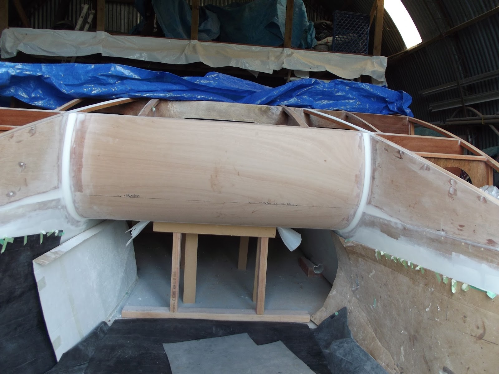
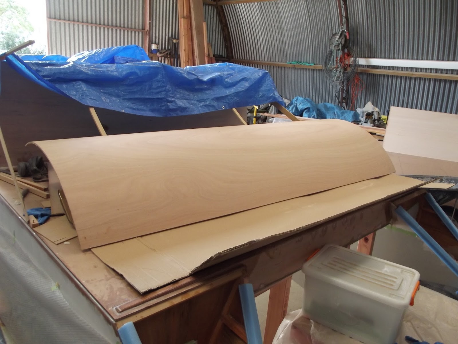
The front of the cabin can be either a flat angled panel or a curved section as shown. The main dimensions for the curve are dictated by the front to back curved bulkheads which hold it all together, all as per plans.On thinking about how to achieve it I decided to make the whole oversize curved  panel up on a jig, or frame, and then create a pattern on the boat itself using the same jig, temporarily attached to the boat , and adding lots of strips of wood with the hot melt glue gun to identify the finished outer edges of the panel. On the photo of the jig with the strips, some of the strips have already been dismantled, as I realised too late that I should have shown it clamped on the front of the BH2 cabin panel, but you can get the idea.Worked out pretty well, but probably more photos of the process would have been good


. The panel itself is 2 thicknesses of 4mm ply laminated together.


July 2013

The rear crossbeam supposedly gets assembled in situ, by the plans, but I decided to make the beam up on my workbench and fit it in one go. It is a combination of ply with timber inside it. I put a small curve ,side to side, across the top just for fun. I had to make up a jig for my router to cut the slots in the deck so the beam could drop into place. Some of the stringer woodwork inside the upper hulls was also in the way of the beam so I had to rout out a bit on the edges of the beam here and there. Cutting with the router and a jig is much tidier, but of course cuts could be made by hand, or in some cases, a jigsaw.

As regards the cabin, there are two sizes shown in the plans depending whether a larger cabin is wanted, or a larger cockpit. I chose the standard smaller cabin, larger cockpit since I knew I would be mostly using the boat for day sailing. Even so there is enough room in the cabin to sleep 2 not to mention the possibility for a boom tent over the 1.8 m long cockpit. I also think the boat will look more balanced with the smaller cabin.

With the 2 large front cabin bulkheads, (the upper parts of BH2 and 3) I decided to make them as one full panel each, which meant making up patterns from MDF board to avoid expensive errors.
 The BH2 and BH3 upper panels are made up full width to match the width that the boat has ended up at, minus the thickness of the cabin outer wall ply each size. They extend through the deck (with a slot) down to the bridgedeck.

The deck had to be slotted with the router much like as per the rear beam. Parts of the bottom edge of these panels have to have rebates where they meet the bridgedeck support stringers, and also at the edges where they go through the deck to allow for the stringers there. Plus the heavy stringers that transverse the base have to have a small rebate at the back of them where they also meet the above mentioned bridgedeck support stringers, similar to with the rear crossbeam. The openings through the front BH2 panel I made about the size per the plans but with a large opening in the centre .

 A lot of the deck of the boat inside the cabin can now be cut away as the bridge deck becomes the cabin floor. I left a bit of a lip all around the remnants of the deck panel about the width of my jigsaw base against the bulkheads and a bit more on the outer cabin wall edge. It was just easier to keep everything tidy like this as cutting off flush would damage the ply and timber beside it.
With these 2 panels fitted the boat has taken on a very ungainly appearance, especially from the front view. Let’s hope it improves as we progress.